
How to Design an RC Snubber to Protect Relays from Inductive Spikes from AC Motors
- Jun 10
- 11 min read
General Instructions
Use this parametric design guide to create a functional, and safe, resistor-capacitor (RC) snubber circuit for use with 120 VAC 60 Hz single-phase motors that are controlled by an upstream switching device.
Who should use this design guide
This design guide is meant for hobbyists, circuit designers, and engineers who are designing an RC snubber from scratch or analyzing an existing design.
Use-case and circuit topology
Use this design guide for RC snubbers that run parallel to the load (e.g., AC motor), both of which are controlled by an upstream switching device (e.g., relay, MOSFET, BJT, or manual switch). Refer to appendix A for circuit topology.
Constraints, limitations, and assumptions
Snubber resistor must be between 47 ohms and 120 ohms
Snubber capacitor must be between 0.10 µF to 2.2 µF
Inductive load (e.g., AC motor) must draw between 0.15 A rms and 4.71 A rms with a power factor of approximately 0.67 (typical for small single-phase AC motors), includes 1/6 HP, 1/8 HP, and 1/10 HP motors
How to use the design guide
Follow the instructions below which use simple calculations and graphs to parametrically analyze and design an RC snubber circuit. Since the process of designing RC snubber circuits is iterative, the worksheet contains three columns labeled “pass” for multiple iterations, i.e., Pass 1, Pass 2, and Pass 3.
Shortcut! Appendix B contains nine RC snubber designs that were created using this design guide and cover a range of motor currents that may be used by as-is, or as reference. Component recommendations are provided.
Accuracy of design guide
The design guide uses data and results from SPICE (see appendix A for specifics) to inform design choices. Accuracy is limited to the combined error of the simulated circuit layout, component models, and the SPICE simulator itself.
The design guide will produce a conservative, functional RC snubber circuit that is safe for use with AC mains.
Results should be independently verified for safe and effective operation.
Required information
The designer will need the following information to use this guide:
Expected AC motor current
Datasheet for snubber capacitor (or prospective one)
Datasheet for switching device (or prospective one)
Datasheet for snubber resistor (or prospective one)
Designers starting from scratch might consider the following component recommendations.
Relay: Omron G7L
Snubber capacitor: Kemet R46 X2-rated
Snubber resistor: Ohmite PulsEater, Ohmite OX/OY, Bourns PWR163, Bourns PWR220, Bourns PWR263, Vishay CRCW-HP, and Vishay D2TO35
Design tips and RC snubber characteristics
Large motor loads require larger snubber capacitors (usually 0.47 µF or above), small loads can use smaller snubber capacitors
X-rated snubber capacitors should (must) be used for safety when operating from AC mains
Choose a relay/switching device with a rating of 5 to 10 times the current rating of the steady-state AC motor current so it can handle both the load and snubber inrush currents
Use larger resistor values to reduce ringing when the relay/switching device opens and to also reduce inrush current when the relay/switching device closes
Use smaller resistor values to reduce pulse energy (and resistor package size) when the relay/switching device opens
Use smaller resistor values when paired with larger capacitors to reduce resistor heating during steady-state operation
Use larger capacitor values to reduce inductive voltage spikes when the relay/switching device opens
Worksheet (use with instructions below)

Specific Instructions
Line 1. Steady-state load current
Enter the planned steady-state current of the load. For variable loads, enter the largest steady-state current the load might require.
Line 2. Test voltage of snubber capacitor
Enter the test voltage of the snubber capacitor from the device’s datasheet, but not more than 1,500 V peak, on this line (to stay below cable insulation breakdown voltages and relay/switching device impulse withstand voltages). For X-rated capacitors (recommended), this value is listed as the Test Screen Voltage and is shown as an AC voltage (e.g., 1,500 VAC). For non-X-rated capacitors, this value is listed simply as Test Voltage and is usually a scaled multiple of the rated DC voltage.
Line 3. Capacitor value
Choose a snubber capacitor value by using the figures below along with the values from line 1 (steady-state load current) and line 2 (capacitor test voltage). It is recommended to choose the smallest value capacitor that keeps the snubber capacitor's peak value as high as possible, but below the value on line 2. Interpolation between plots may be necessary if the expected load current is between those shown in the figures.
Notice: the snubber resistor value doesn't impact the snubber capacitor's voltage much, so assume the smallest resistor value for now (for worst case snubber capacitor voltage). The value for the snubber resistor will be determined later.


Line 4. Maximum current available when relay closes
Enter the amount of current the relay could supply to the snubber circuit when the relay first closes. Note: the snubber is an RC circuit that will draw an inrush current when the relay closes. This step will help determine if the relay has enough capacity to supply current to both the load and snubber when the relay closes.
The value entered on this line represents the difference between the relay’s rated current and the load current when first energized. Some loads, particularly motors, have large inrush currents when first energized that are much higher than their steady-state current. For example, the following figure from Panasonic shows a typical motor inrush current.
![Typical motor inrush current [source: Panasonic]](https://static.wixstatic.com/media/759dbd_497e4ebc8fdc4d669a49b00fe12f62d5~mv2.png/v1/fill/w_80,h_73,al_c,q_85,usm_0.66_1.00_0.01,blur_2,enc_avif,quality_auto/759dbd_497e4ebc8fdc4d669a49b00fe12f62d5~mv2.png)
For example, assume a 30 A relay is powering both the snubber circuit and the load, and that the load draws 27.5 A of inrush current when energized. The difference between 30 A and 27.5 A is 2.5 A. The peak of this value (2.5 A times 1.414 = 3.54 A pk) would be entered on this line.
For this design guide, the minimum value allowed to be entered on this line is 1.414 A pk (due to the allowable range of snubber resistors, i.e., 47 ohms to 120 ohms). If the relay cannot supply at least this much instantaneous current to the snubber circuit, this guide cannot be used: STOP and consider using a larger relay, if possible.
Line 5. Calculate snubber resistor option #1 at relay closure
Calculate snubber resistor option #1 at relay closure using the following equation: (120 Vrms * 1.414) / line 4 value. If the calculated resistance is less than 47 ohms, enter 47 ohms on this line.
Line 6. Calculate snubber resistor option #2 at relay open
Calculate snubber resistor option #2 at relay open using the following equation: 120 Vrms / line 1. This value can be no higher than 120 ohms or less than 47 ohms.
Line 7. Enter larger of line 5 and line 6
Enter the larger of resistor values from line 5 and line 6.
Line 8. Snubber resistor value
Enter a real resistor value that is the same or next higher value to line 7, for example: 47, 50, 56, 75, 100, and 120 ohms.
Line 9. Calculate snubber capacitor impedance
Calculate snubber capacitor impedance using the following equation: 1 / (2 * pi * 60 Hz * line 3). Caution: convert line 3 to Farads for correct results (it’s shown in microfarads in the worksheet. Convert to Farads by multiplying line 3 by 1,000,000).
Line 10. Calculate snubber circuit impedance
Calculate overall snubber impedance using the following equation: sqrt((line 8)^2 + (line 9)^2).
Line 11. Calculate snubber circuit current
Calculate snubber current by dividing 120 Vrms by the value on line 10.
Line 12. Calculate steady-state power of snubber resistor
Calculate the steady-state power dissipated by the snubber resistor using the following equation: (line 11)^2 * line 8.
Line 13. Snubber resistor Rthj-a
Enter Rthj-a for the snubber resistor. This value can be found in the device's datasheet or in the tables below with approximate values.

Line 14. Calculate steady-state snubber resistor temperature
Calculate the steady-state temperature of the snubber resistor using the following equation: 25 + (line 12 * line 13).
Recommendation: A component is generally too hot for conservative designs when a person is unable to touch it for more than one second without experiencing pain and pulling away, per the 60-6, 70-1 rule: a surface of 60 degrees Celsius can be touched for 6 seconds before experiencing pain, and a surface of 70 degrees Celsius for 1 second before experiencing pain.
Decision point: if the value calculated for line 14 is greater than 70 degrees Celsius, STOP – the snubber resistor will get too hot during steady-state operation (for conservative designs). A lower Rthj-a is required to decrease heating. This can be achieved by choosing a resistor package with a lower Rthj-a and/or adding heat-
sinking to the printed circuit board or through-hole component. Once a new Rthj-a is achieved, loop back to line 13 for another iteration.
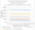
Line 15. Snubber resistor pulse characteristics at relay closure
Enter the snubber resistor's pulse characteristics using the figures below along with the snubber resistor value from line 8 and the snubber capacitor value from line 3. Use line 15a to enter the snubber resistor's pulse power at relay closure using the first figure below, line 15b for the resistor's pulse energy using the second figure below, and line 15c for the resistor's pulse duration using the third figure below.


Line 16. Snubber resistor pulse characteristics from datasheet
Enter the snubber resistor's allowable pulse value from the device's datasheet using the pulse duration from line 15c. The datasheet normally shows this value in a figure called Overload Duration in Seconds. Some datasheets use units of Watts, and others use units of Joules. If Watts, enter the maximum pulse value from the datasheet figure in line 16a and leave line 16b blank. If Joules, enter the maximum pulse value from the datasheet figure in line 16b and leave line 16a blank.
Decision point: if the value on line 15a is greater than the value on line 16a, or if the value on line 15b is greater than the value on line 16b, whichever applies, STOP - the snubber resistor cannot handle the pulse at relay closure. Choose a different resistor package and loop back to line 13 for another iteration (because the new resistor package may have a different Rthj-a).
Line 17. Snubber resistor pulse characteristics at relay open
Enter the snubber resistor's pulse characteristics using the figures below along with the snubber resistor value from line 8, the snubber capacitor value from line 3, and the steady-state load current from line 1. Use line 17a to enter the snubber resistor's pulse power at relay open using the first set of figures below, line 17b for the resistor's pulse energy using the second set of figures below, and line 17c for the resistor's pulse duration using the third set of figures below. Interpolation between plots may be necessary if the expected load current is between those shown in the figures.
Figure set #1: Snubber resistor pulse power


Figure set #2: Snubber resistor pulse energy
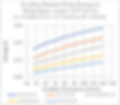


Figure set #3: Snubber resistor pulse duration


Line 18. Snubber resistor pulse characteristics from datasheet
Enter the snubber resistor's allowable pulse value from the device's datasheet using the pulse duration from line 17c. The datasheet normally shows this value in a figure called Overload Duration in Seconds. Some datasheets use units of Watts, and others use units of Joules. If Watts, enter the maximum pulse value from the datasheet figure on line 18a and leave line 18b blank. If Joules, enter the maximum pulse value from the datasheet figure on line 18b and leave line 18a blank.
Decision point: if the value on line 17a is greater than the value on line 18a, or if the value on line 17b is greater than the value on line 18b, whichever applies, STOP - the snubber resistor cannot handle the pulse. Choose a different resistor package and loop back to line 13 for another iteration (because the new resistor package may have a different Rthj-a).
Line 19. Snubber resistor pulse voltage at relay closure
Enter 164.3 V on this line. This value is unaffected by the load and snubber capacitor value.
Line 20. Snubber resistor pulse voltage at relay open
Enter the snubber resistor peak voltage when the relay opens using the figures below along with the snubber resistor value from line 8, the snubber capacitor value from line 3, and the steady-state load current from line 1. Interpolation between plots may be necessary if the expected load current is between those shown in the figures.


Line 21. Enter larger of line 19 and line 20
Enter the larger of resistor pulse voltages from line 19 and line 20.
Line 22. Overload or impulse voltage from datasheet
Enter the snubber resistor's allowable overload or impulse voltage from the device's datasheet. Some datasheets show this value as Overload Voltage, which is usually a multiple of the Maximum Operating Voltage. Other datasheets show this value as Maximum Pulse Voltage or Impulse Voltage.
Decision point: if the value on line 21 is greater than the value on line 22, STOP - the snubber resistor cannot handle the impulse voltage. Choose a different resistor package and loop back to line 13 for another iteration (because the new resistor package may have a different Rthj-a).
Line 23. Snubber (and load) peak voltage at relay open
Enter the snubber (and load) peak voltage when the relay opens using the figures below along with the snubber resistor value from line 8, the snubber capacitor value from line 3, and the steady-state load current from line 1. Interpolation between plots may be necessary if the expected load current is between those shown in the figures.
Decision point: if the value on line 23 is greater than the designer would like (due to concerns about cable insulation breakdown voltages and relay/switching device impulse withstand voltages), or if it's above 1,500 V peak, STOP - the snubber capacitor should be increased to lower this voltage. Choose a larger capacitor value and loop back to line 3 for another iteration.


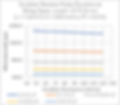
Line 24. Snubber (and load) oscillation characteristics at relay open
Enter the snubber (and load) oscillation characteristics when the relay opens using the sets of figures below along with the snubber resistor value from line 8, the snubber capacitor value from line 3, and the steady-state load current from line 1.
Use line 24a to enter the snubber (and load's) oscillation frequency at relay open using the first set of figures below. Use line 24b to enter the number of oscillation cycles that are above 120 Vrms using the second set of figures below. Interpolation between plots may be necessary if the expected load current is between those shown in the figures.
Decision point: if the values on lines 24a or 24b are unsatisfactory to the designer (due to EMI or load concerns, for example) STOP – either, or both, of the snubber resistor and capacitor should be changed as follows: an increase to snubber resistance will decrease the number of oscillation cycles, but will not change the oscillation frequency; an increase in snubber capacitance will decrease both the oscillation frequency and the number of cycles. If changing the snubber resistance value, loop back to line 8 for another iteration (note: snubber resistance cannot exceed 120 ohms for this design guide). If changing the snubber capacitance value, loop back to line 3 for another iteration.
Figure set #1: Snubber (and load) oscillation frequency


Figure set #2: Snubber (and load) oscillation cycles above 120 Vrms


Appendix A: Simulation Model
SPICE program: LTspice XVII(x64) (17.0.32.0) Oct 28 2021


Appendix B: Results & Component Recommendations
The following results were produced from the RC snubber design guide for motor currents ranging from 0.15 Amps to 4.71 Amps, including 1/6 HP, 1/8 HP, and 1/10 HP motors.

1. Vishay D2TO35, D2PAK package
2. Vishay CRCW-HP, 2512 package
3. Vishay CRCW-HP, 1210 package
4. Vishay CRCW-HP, 1206 package
References and Notes
Derived from ST application note AN1703, dated June 2003, figure 3 minimum recommended footprint plus Rthj from Bourns PWR263-20 resistor datasheet
Derived from ST application note AN1703, dated June 2003, figure 6 minimum recommended footprint plus Rthj from Bourns PWR163 resistor datasheet
Provided by Vishay Sfernice application note 53048 revision 29-Oct-09, table 1, sCu (Nat) column, Rthj-a
Derived from Ohmite PulsEater A Series datasheet revision 5/22-1 pages 52-53
Derived from ST application note AN1703, dated June 2003, page 4 paragraph 1 plus Rthj from Bourns PWR220T-20 resistor datasheet
Derived from Ohmite OX/OY Series datasheet revision 4/20-1 pages 56-57